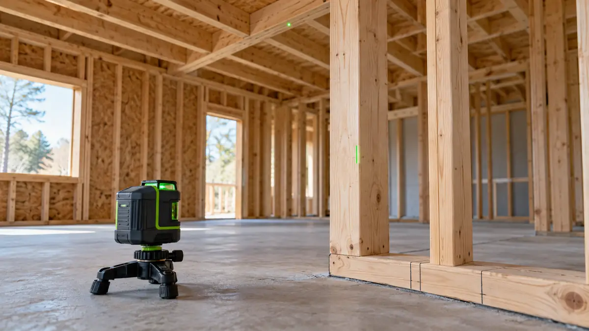
Learning how to use a laser level for framing starts with a defined line, height, or plumb position that the surfaces need to share. Establish the control marks first, position the instrument against those marks, and verify the transferred positions before construction hides them. The laser helps carry the layout; it does not determine the framing design.
Separate the questions you are checking. A wall can be plumb without being in the intended location. Matching heights do not prove a floor frame is structurally correct. A vertical point transfer does not locate wiring or pipes behind a surface.
Once the required transfer is clear, compare laser levels for framing layouts by the reference geometry and positioning arrangement. A local wall cross, continuous planes, and dedicated point functions solve different parts of the job.
How to Use a Laser Level for Framing: Preserve the Control
Begin with the approved plan and a control line or datum that can be recognized again. Record whether a mark describes a wall centerline, a finished face, an elevation, or an offset used for measuring. Those descriptions prevent an accurate transfer of the wrong reference.
Place preserved marks where they will remain accessible while plates, studs, boards, and services are installed. If the only control disappears beneath the first component, later checks become dependent on assumptions about that component.
Do not rely on the building around you as an unverified substitute. An existing floor may change elevation, a corner may not be square, and a ceiling edge may not be level. Establish which conditions the project intends to retain and which the new layout must independently satisfy.
Choose a Transfer Method for the Mark
| Layout question | Reference to investigate | Independent check |
|---|---|---|
| Where does an overhead position relate to a floor mark? | Documented plumb-transfer function | Correct positioning over the floor control and suitable point accuracy |
| Do several marks share the intended height? | Horizontal line or plane | Connection to the preserved height datum |
| Is a wall element plumb? | Appropriate vertical reference | Required offsets measured consistently along the element |
| Does a layout meet the intended right-angle relationship? | Documented geometry and a suitable layout method | Project dimensions and an independent check appropriate to the work |
Check the exact instrument instructions for orientation and positioning. A forward-facing point is not automatically a plumb-up point, and an intersecting line pattern does not justify treating every visible corner as a verified square layout.
Transfer Framing Positions Without Losing Their Meaning
- Confirm the approved reference. Identify the control line, elevation, or point and the component relationship it represents.
- Position the instrument securely. Keep it outside likely knocks, timber movement, and the immediate fixing path.
- Establish the documented working mode. Check leveling status, point direction, and relevant orientation before marking.
- Transfer a small number of identifiable marks. Label the reference or its offset rather than creating an unexplained collection of ticks.
- Compare the result with the project dimensions. Confirm that the correct surfaces and faces have been related.
- Recheck after work changes the setup. Return to the preserved control after a move, disturbance, or other event that invalidates the reference.
Where a vertical reference is offset from a frame, measurements to it can help compare the frame’s position at different heights. Keep the measuring direction and intended offset consistent. A tapering gap may reveal a relationship that needs investigation, but the laser does not specify the correct structural adjustment.
Record the Transfer, Not Just the Result
For an overhead point transfer, label the starting floor control and the corresponding overhead mark as a pair. If an offset was used to keep the instrument clear of a component, record that relationship as well. Someone checking the work should be able to tell which mark was transferred and which was calculated from it.
Before the frame changes, compare critical transferred marks with the original control and the intended dimensions. Repeating an instrument operation is not an independent check if both attempts begin from the same mistaken starting point.
Electrical Layout: Transfer Positions, Not Assumptions
For wall boxes or related marks, decide whether the design is controlled by a common elevation, a finished-floor dimension, a fixture position, or another requirement. A horizontal reference can help relate those marks across a room, provided the measurements all use the same basis.
The laser levels for electrical layout comparison focuses on references and equipment arrangements. It does not establish required electrical heights, clearances, safe drilling positions, or the absence of concealed services. Those decisions belong to the applicable design and qualified work procedure.
Suspended Ceilings: Distinguish the Datum From the Grid
A perimeter reference can help transfer the planned ceiling elevation between walls. The actual grid system still has hanger, clearance, support, and installation requirements, and the visible reference may sit at a deliberate offset from the component being installed.
Compare laser levels for suspended ceiling layout when the practical issue is carrying that reference at working height. A supplied grid clamp may be relevant, but it needs to suit the system and its intended use rather than being treated as a universal overhead attachment.
Plumbing Rough-In: Label What Each Mark Represents
A mark for a pipe center, a support, a finished fixture, and a penetration can describe different positions. Confirm the intended relationship before transferring it. Repeatedly measuring the same offset accurately is no help if the wrong fixture dimension was used at the start.
The laser levels for plumbing layout guide compares the reference arrangements available for that marking work. It does not turn a level line into an approved pipe gradient or replace the plumbing system’s installation requirements.
Floor Joists: Compare the Required Reference Surfaces
A horizontal reference can help compare relative heights at identified points on a frame. Record which face or bearing relationship is being checked. The top of a member, a hanger mark, and the underside of a finished assembly are not interchangeable measurement surfaces.
These laser levels for floor-joist checks are a useful equipment comparison for that task. Member sizing, support, connections, and corrective work require the appropriate structural information; the instrument only contributes the position reference.
Keep the Later Finish Work Connected
Rough-in marks become more useful when they can be related to the final cabinet, trim, and fixture layout. Confirm finished-floor assumptions and any offsets that must pass between trades. Preserve the control needed for the next phase rather than asking the finish installer to infer it from an unfinished component.
See connecting rough-in marks to the later finish layout for that relationship. If the reference must be carried overhead or placed beside a crowded frame, start with checking the support before transferring overhead marks.
Before covering the work, verify the critical marks against the original control and the approved dimensions. That is the opportunity to catch a mistaken face, forgotten offset, or disturbed setup while the reference is still accessible.
