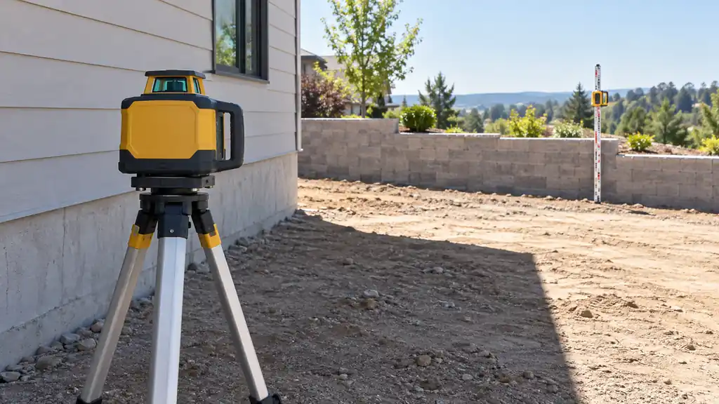
Working out how to use a laser level outdoors means solving two problems: locating the reference in the actual light and transferring a height without losing its connection to a benchmark. A suitable receiver-based setup can address the first problem. Preserved control marks and repeatable station readings address the second.
Do not assume that a green indoor line will remain easy to see across a sunny yard. A receiver can help only when the transmitter supports it and the exact combination is compatible. The tool, receiver, rod, and support need to form a usable system.
Start with laser levels suited to outdoor work, then check what the selected arrangement includes. A long range printed beside an instrument does not tell you whether the necessary receiving equipment is supplied.
How to Use a Laser Level Outdoors: Choose the Reference
Outdoor work does not always call for the same result. You might need a shared elevation at several deck locations, a designed fence relationship along changing terrain, or height checks across a prepared footprint. Decide which relationship the work must preserve before setting the instrument.
A horizontal plane can help compare different elevations. It does not mean every point should finish at the same height. Equally, a project that needs level support must not acquire a drainage slope simply because sloping work is common outdoors.
Establish a Reading Routine You Can Repeat
- Preserve a benchmark. Choose an identifiable stable reference that the ongoing work will not remove or disturb.
- Set the instrument on suitable footing. Leave room for safe station access and keep the tripod away from likely equipment movement.
- Confirm the required mode and compatible receiver. Follow the manufacturer instructions for the particular system.
- Read the benchmark. Keep the rod upright, use the correct receiver index, and record the scale convention.
- Read the identified stations. Record the intended surface or component at each point.
- Reconnect after a move or disturbance. Establish the new setup’s relationship before comparing more readings with earlier ones.
For the measurement details, see reading a receiver and grade rod. Learn the receiver indications close to a known reference before trying to interpret an unfamiliar arrow at a distant station.
Visibility: Check the System, Not Just the Beam Color
Light conditions, surface appearance, distance, and the instrument affect whether a visible line can be located. Changing the work sequence or instrument position may help with access, but it does not extend the tool’s documented capability.
A receiving mode on a compatible line laser and a rotary receiver are not interchangeable categories. Check the exact transmitter and receiver documentation, including any required operating mode. Our guide to verifying the transmitter and receiver combination provides a compatibility checklist.
Keep the beam path away from eyes, vehicles, and reflective directions that create exposure problems. Do not use optical magnification to hunt for a beam, and do not treat visibility-enhancing glasses as protective eyewear. Work within the equipment’s stated environmental limits.
Move Stations Without Losing the Height Relationship
When the instrument stays fixed, the preserved benchmark lets station readings share a reference. If the instrument must move, the new setup may create a different plane height even after automatic leveling is complete.
Before using the new setup, read the same preserved control again, or use an appropriately established transfer point that remained stable and identifiable. Record the relationship for the new setup. Do not combine readings from two instrument heights as though nothing changed.
If the benchmark itself was disturbed, stop treating it as control. Re-establish the reference using the project’s appropriate method. An instrument can be functioning perfectly while the ground mark beneath the measurement has become unreliable.
Deck Layout: Identify the Component Being Checked
A deck project can involve different reference surfaces: supports, framing members, and the intended finished surface do not necessarily share an elevation. Use the approved design and actual component relationships to determine which marks should correspond.
The laser levels for deck layout guide compares equipment for transferring those references. A height check cannot confirm member sizes, connections, foundations, or the required structural arrangement.
Fence Layout: A Shared Datum Does Not Require a Flat Top
First establish the intended fence design along the terrain. A stepped run, a sloping relationship, and a level top create different target positions. A common laser reference helps compare the relevant marks without deciding which design the property should use.
Compare laser levels for fencing when selecting the field setup. Record which mark describes a post, rail, finished top, or offset; otherwise two carefully measured stations can still describe different parts of the fence.
Siding: Carry the Planned Course Relationship
Exterior cladding has product-specific layout, flashing, clearance, and fastening requirements. A height reference can help relate the intended starting course or other control marks across a wall, but it does not establish those requirements or compensate for an unsuitable substrate.
These laser levels for siding installation compare different ways to position and transfer the reference. Keep the datum accessible as boards begin to cover the original marking area.
Retaining Walls: Preserve the Design’s Distinct Targets
A retaining-wall layout may have changes in elevation, steps, and relationships to adjacent finished surfaces. Check the relevant designed points rather than forcing every course or station to a single level merely because the laser can provide one.
The laser levels for retaining-wall layout guide helps compare measurement systems. Structural design, foundation preparation, drainage provisions, and the wall system’s construction requirements remain separate from the laser reading.
Pool Sites: Keep Level Support Separate From Drainage Fall
An above-ground pool must follow its specific site and support instructions. Do not substitute an example drainage slope or a general patio recommendation for the pool manufacturer’s requirements. Check the required footprint and support positions, not just one convenient point at the perimeter.
The laser levels for above-ground pool site checks comparison focuses on equipment for those elevation checks. Measurements alone do not establish bearing capacity, base preparation, or the suitability of material placed beneath the pool. Bestway’s site-preparation guidance starts with the instructions for the actual pool, which is the right place to establish its requirements.
Leave a Record That Survives the Setup
For each set of checks, record the benchmark, setup identity, rod units, receiver setting, station, and surface being measured. A simple sketch can distinguish the top of a component from the ground beside it and help another person repeat the check.
When the work changes the site, return to that record rather than trying to recreate yesterday’s instrument position by eye. The useful continuity comes from a preserved reference and understood measurements, not from placing the tripod in approximately the same patch of grass.
