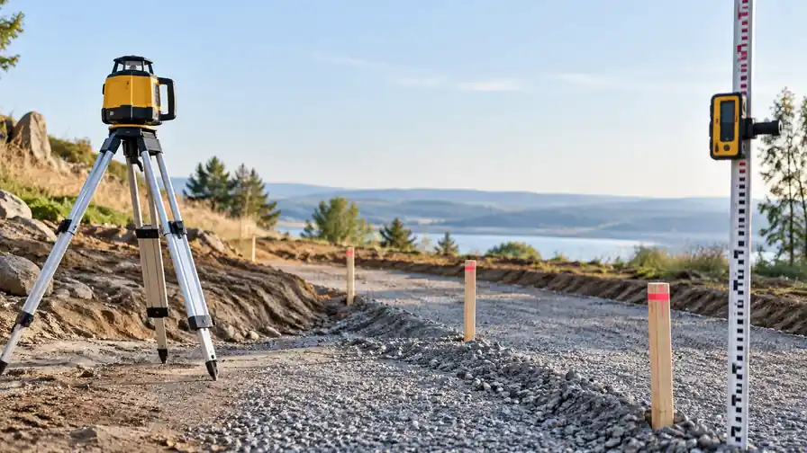
The first step in learning how to use a laser level for grading is identifying the required design elevations or slope. Establish a dependable reference, measure each station against it, and compare the reading with that station's target. The laser helps you check the planned shape; it does not decide which direction or rate of drainage the site should have.
You can use a horizontal reference plane and calculate different rod targets along the run. A system with documented slope control offers another method, but its axes, setup, and checks must match the intended design. Those methods should not be mixed without understanding which reference is being used.
Our laser levels for grading and drainage compare receiver-based systems and relevant control capabilities. Start with the measuring routine you need, then check the exact instrument and package rather than choosing from beam visibility alone.
How to Use a Laser Level for Grading: Define the Target
Obtain the project elevations, direction of fall, drainage destination, and applicable construction requirements. A patio beside a house, a landscape swale, and a prepared pad do not share one universal slope prescription. Existing property conditions and the approved design control the target.
Identify the run over which a slope is specified. Use consistent horizontal distances and units. Keep percentage, decimal ratio, degrees, and an amount of fall per unit length distinct: a percentage value cannot simply be entered into a degrees control as the same number.
Also distinguish a surface target from an intermediate construction layer. The elevation of a finished paver, the bedding layer, and the compacted base are related through the actual build-up. The measuring tool cannot supply those material thicknesses or installation requirements.
Choose Between Two Measuring Arrangements
| Arrangement | Reference | What changes along the run |
|---|---|---|
| Horizontal plane with calculated targets | The laser stays in its horizontal-reference mode | Required rod readings change with target elevation |
| Documented slope-control setup | The reference is inclined according to the supported method | The relationship must be checked against the designed grade and correct axis |
The horizontal method is easy to understand because each reading relates to one plane. Before using the examples below, review establishing a rotary benchmark and receiver reading. The calculations assume a conventional upright rod graduated upward from its foot and readings taken at the receiver’s correct index.
Calculate the Fall Without Mixing Units
The basic relationship is fall = horizontal run × slope as a decimal. As a worked arithmetic example only, assume a design calls for 2% fall over a 20-foot horizontal run. Two percent is 0.02, so the calculated fall is 0.40 feet, equivalent to 4.8 inches.
That example is not a drainage recommendation for your property. Its purpose is to show the unit conversion. If the project specifies another slope, a different direction, or a particular elevation at the end, those requirements replace the example.
Write the starting and ending targets down before moving material. “Lower at the far end” is too vague to check, while a stated target elevation lets you compare the same station again as work progresses.
Convert the Targets Into Rod Readings
Suppose, hypothetically, a horizontal reference plane is at 104.25 feet in a local datum system. The starting target elevation is 100.00 feet. Applying the example fall gives these target readings:
| Horizontal distance from start | Target elevation | Target rod reading |
|---|---|---|
| 0 ft | 100.00 ft | 4.25 ft |
| 10 ft | 99.80 ft | 4.45 ft |
| 20 ft | 99.60 ft | 4.65 ft |
All values in this table use decimal feet. The target reading grows as the target surface falls farther below the horizontal plane. Compare the measured station elevation with the target elevation before deciding what correction is needed; that avoids reversing the meaning of a larger rod reading.
For example, at the last station a measured reading of 4.50 feet would give an elevation of 99.75 feet. That is 0.15 feet above the hypothetical target of 99.60 feet. It describes a measured difference, not an instruction to remove material without considering which construction layer and requirements are being checked.
Check the Run in a Repeatable Sequence
- Preserve and identify a benchmark outside the work likely to disturb it.
- Establish the instrument’s required reference and record the benchmark reading.
- Identify the measurement stations and their design targets.
- Hold the rod upright on the intended surface and read at the proper receiver index.
- Record actual reading, target, and the construction layer being checked.
- Return to control after disturbance or a setup change before relying on more readings.
Do not change the receiver’s sensitivity or scale convention midway through a record without noting it. A different on-reference band can change how finely a station is being judged, even when the display appears to give the same simple result.
When a Slope-Capable Rotary System Helps
Some projects benefit from an instrument with documented single-axis or dual-axis slope functions. Verify how the design direction is aligned to the instrument, which axes are controlled, and how the chosen model establishes the intended inclination. A remote may change controls without confirming that the reference matches the project.
Compare rotary lasers with documented slope functions by those operating differences. A locked manual line, a button that tilts a reference, and a system that accepts a numeric grade are not automatically equivalent methods.
Apply the Reference to the Actual Outdoor Task
In landscaping, different areas can have different targets and surface build-ups. A single grade check does not describe the entire yard. The laser levels for landscaping guide compares equipment for that wider reference work, including the supports and receivers needed to read stations.
For a patio, keep the finished-surface plan separate from intermediate layers and perimeter conditions. These laser levels for patio projects help compare measuring arrangements; the paving system and drainage design establish what those measurements must satisfy.
A task requiring level support, such as a pool installation under its manufacturer’s requirements, must not inherit an illustrative drainage slope. Decide whether the job is checking level, a specified elevation difference, or an intentional grade before starting the calculations.
Protect the Benchmark as the Site Changes
A rod foot sinking into loose material, a disturbed stake, or a tripod shifted out of the work path can invalidate the comparison. Use a stable, identifiable point appropriate to the measurement and reconnect after any setup change.
Our guide to maintaining an outdoor reference between stations explains that part of the routine. Keep the final readings with the design targets and setup notes so a later check can reproduce the relationship instead of relying on a remembered beep.
